After I replaced the defective VCF/VCA IC on my Juno 106, I always felt the urge to take a look into this hybrid IC, in order see what components Roland has been using for the filter and the VCA.
I tried several ways to remove the enveloping compound covering the chip.
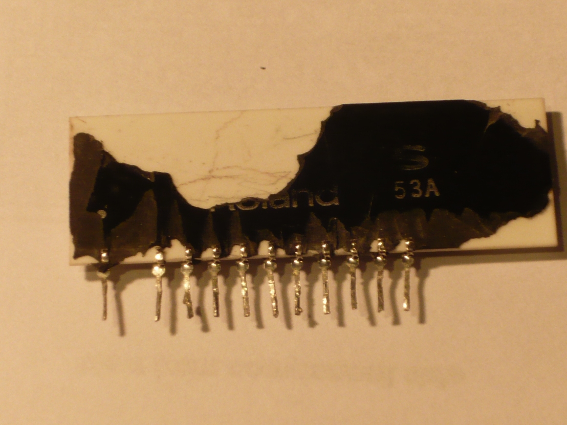
First I tried with a sharp knife to break of the lacquer which didn’t work out and is pretty dangerous too, then I tried dissolving it with paint thinner without any effect at all.
Finally, I tried out some Acetone, where I left the component in over night, and this seemed to penetrate into the compound, making it flexible and eventually coming off by gently poking around with a sharp screwdriver. Curiously, neither the SMD IC’s nor the fiberglass PCB got damaged by this process and I was left with a nicely stripped down board.
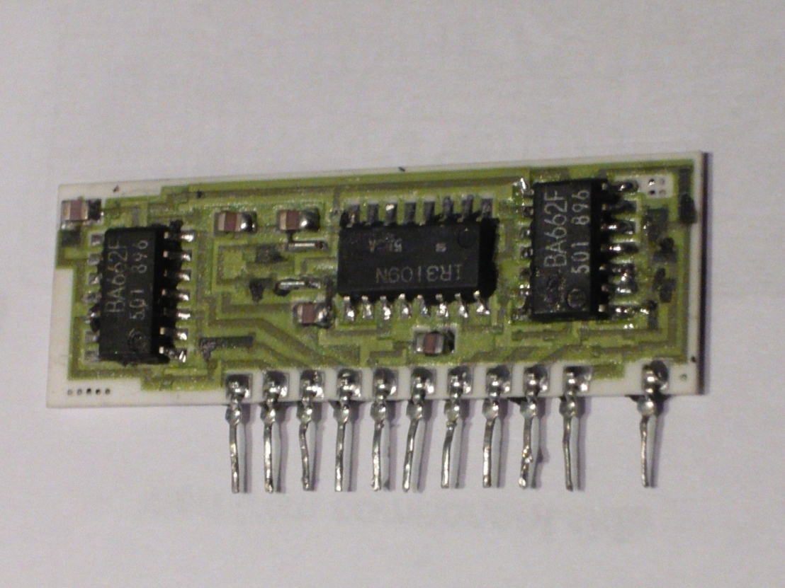
The resistors on the board are made via a printing process, thus not replaceable, the SMD’s could be replaced but are long obsolete.
Since now we know what’s going on inside these chips, we can do a quick research on the inner workings.
Just to note, my intention was not to produce a copy of this VCF/VCA since there are some very good clones already around, but to take a look inside and build some general understanding what makes this circuit so special.
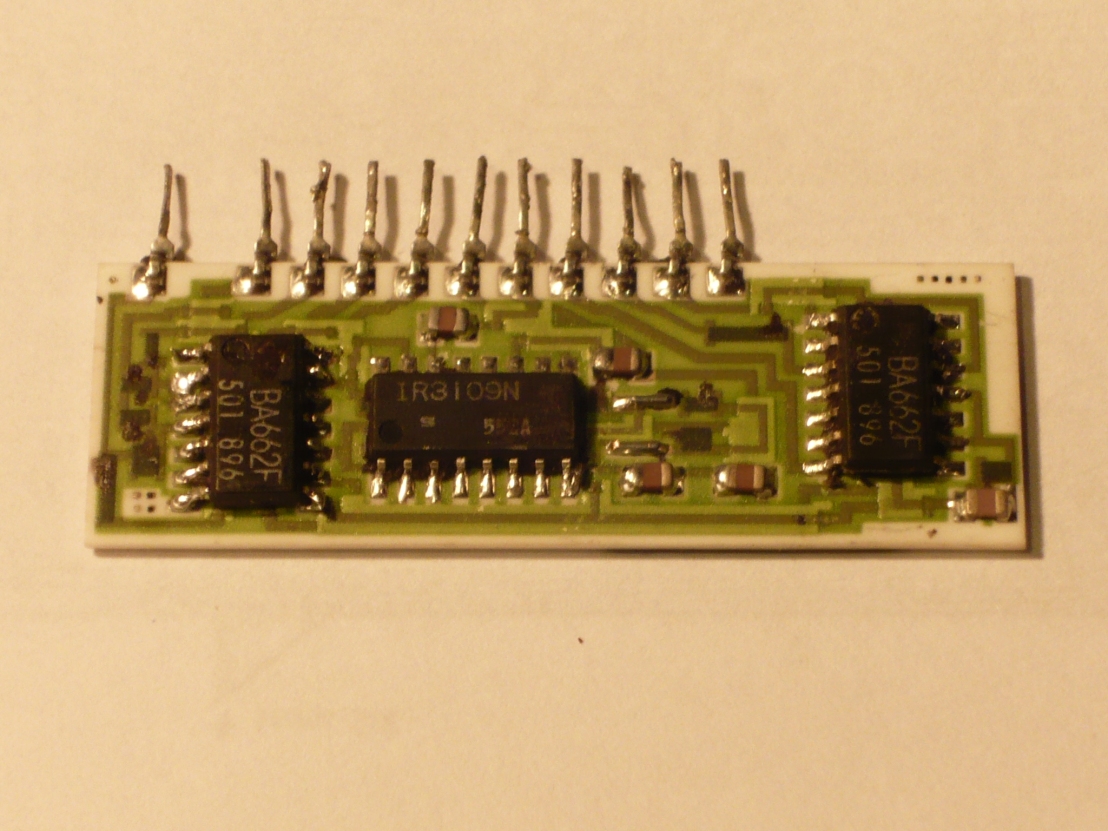
We are accounting for one IR3109 and two BA662, several SMD Capacitors and some printed resistors.
The IR3109 is a long obsolete, quad OTA with buffers and onboard exponential converter. Here, in this configuration, the IR3109 is wired up as a filter with a slope of 24db/oct.
One BA662, which is a voltage controlled amplifier, is responsible for the resonance control of the filter, the other one is the VCA for amplitude control.
80017A Overview out of the Juno 106 Service manual:
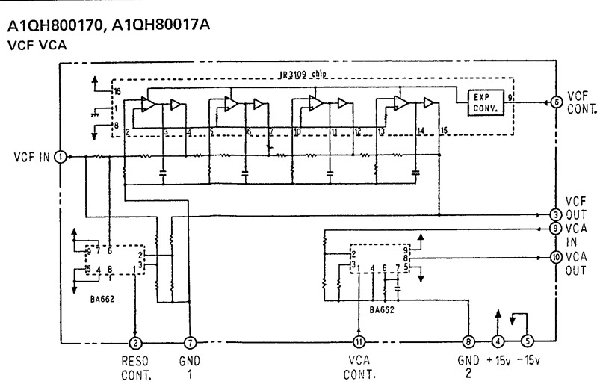
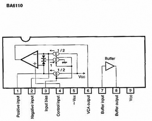
The BA662 is a voltage controlled amplifier, also obsolete, and I did not find too much information about it except a pinout in the TB303 service manual and a reference to the newer BA6110 which has a similar function.
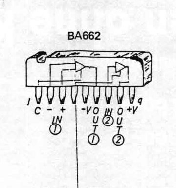
At least the BA6110 datasheet is still available, so here the overview of the package:
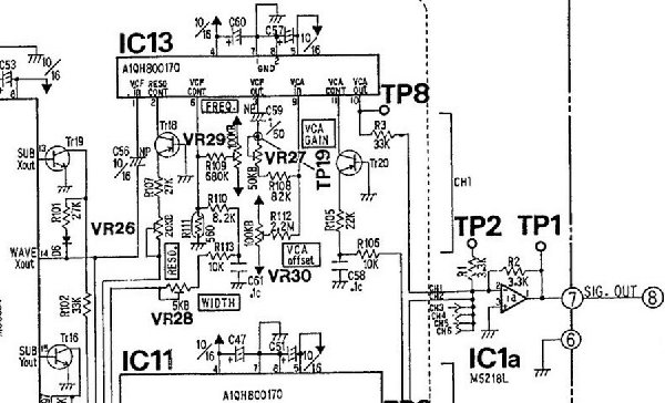
Now let’s take a look how the 80017A is wired up inside a Juno106
We can directly compare with the filter/vca section of a Juno 60:
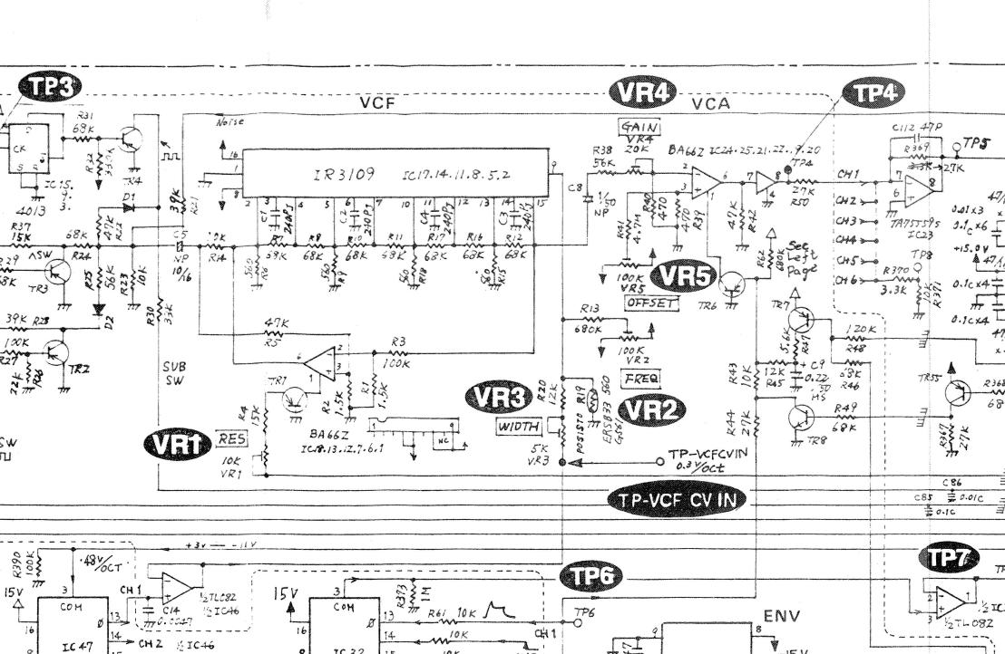
The interesting part is, that the Juno 60 uses exactly the same parts for filter and VCA as the Juno 106 does, except for the hybrid packaging.
The values for capacitors and resistors for the filter can thus be taken from the Juno 60 schematic. Also the values for the resonance control VCA and amplitude VCA can probably be simply copied.
To reproduce such a filter/vca combination nowadays, one would probably be better off to use some of the OTA’s still remaining in production by today, like the dual OTA LM13700, or some CA3280’s.
Otherwise, the THAT VCA’s might be a good alternative for VCA replacements .
The only thing which is still missing would be the exponential converter, which could be build from a dual transistor like a BC847, but it would need to be placed near the Filter OTA’s in order to follow temperature evolution and to keep a good tracking.
The use of a tempco resistor, of course would improve temperature tracking even more.
