If you use a lot of oldschool drum machines, you will probably get to the point where you will want to synchronize your drum machine to some other kind of sequencer, be it software or hardware.
That’s when you find out that you need a Midi to Sync converter.
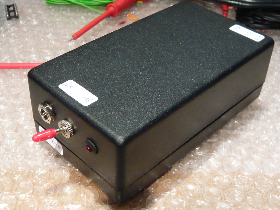
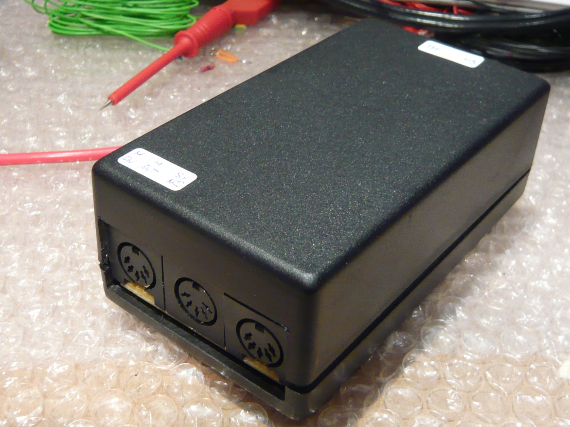
Another picture to show the connector in/outputs:
Here, I used a PIC16F628 microcontroller with integrated serial port and I wrote some code which can convert MidiSync messages to DinSync (24 ppqn as per Roland standard) and also DinSync to Midi Sync.
In Midi-Sync mode I also added a 12ppqn clock output and optionally a 48ppqn output to link up with old Korg drum machines as KPR77 for example.
In order to use the 48ppqn output you will need to add the commented out part for the 48ppqn clock generation and recompile the code.
Note that in this case the maximum clock speed will be limited to about 200 bpm, beyond that rate, the clock signal will show a serious amount of jitter.
Before, I spent a lot of time trying out various methods of bit-banging an PIC16F84 running at 4MHz, in order to simulate a serial input. My code worked well, but I always had a feeling that the amount of jitter produced was quite too high, therefore I decided to go with an F628 which has already a built in USART port, which of course makes things a hell lot simpler.
Also it is worth noting that the quality of the generated sync signal is depending a lot on the precision of the Midi sync signal fed into the system. Furthermore I would recommend using a dedicated midi output port for the midi sync signal, additional traffic on the midi port like midi note messages and Sysex will contribute to additional jitter.
There are also some drum machines which will send midi note messages along with the midi sync signal and it is generally a good idea to turn this transmission off if not needed and possible of course.
Personally, I like the Sync-Midi mode best, it enables me to use my TR808 as a master clock for my software sequencer. I always have a feeling that the computer generated MidiSync signal is a bit untight, therefore this mode comes handy. In Ableton live, the one thing to keep in mind is to turn the ‘warp’ feature off after recording some tracks if you like to keep the original groove for further mixing.
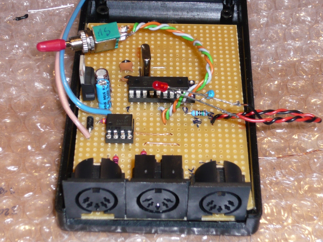
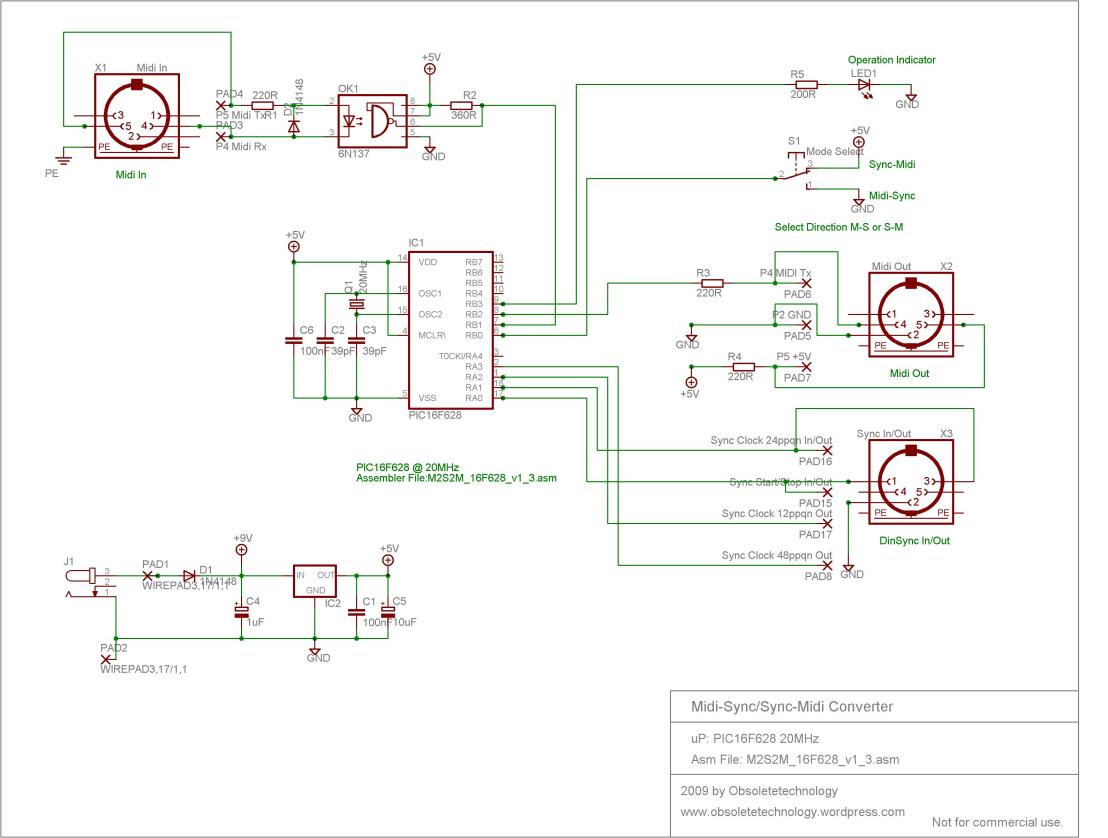
The schematic is pretty straightforward, just one microcontroller running at 20MHz, an optocoupler as per midi specification and some more parts for power supply and connectors.
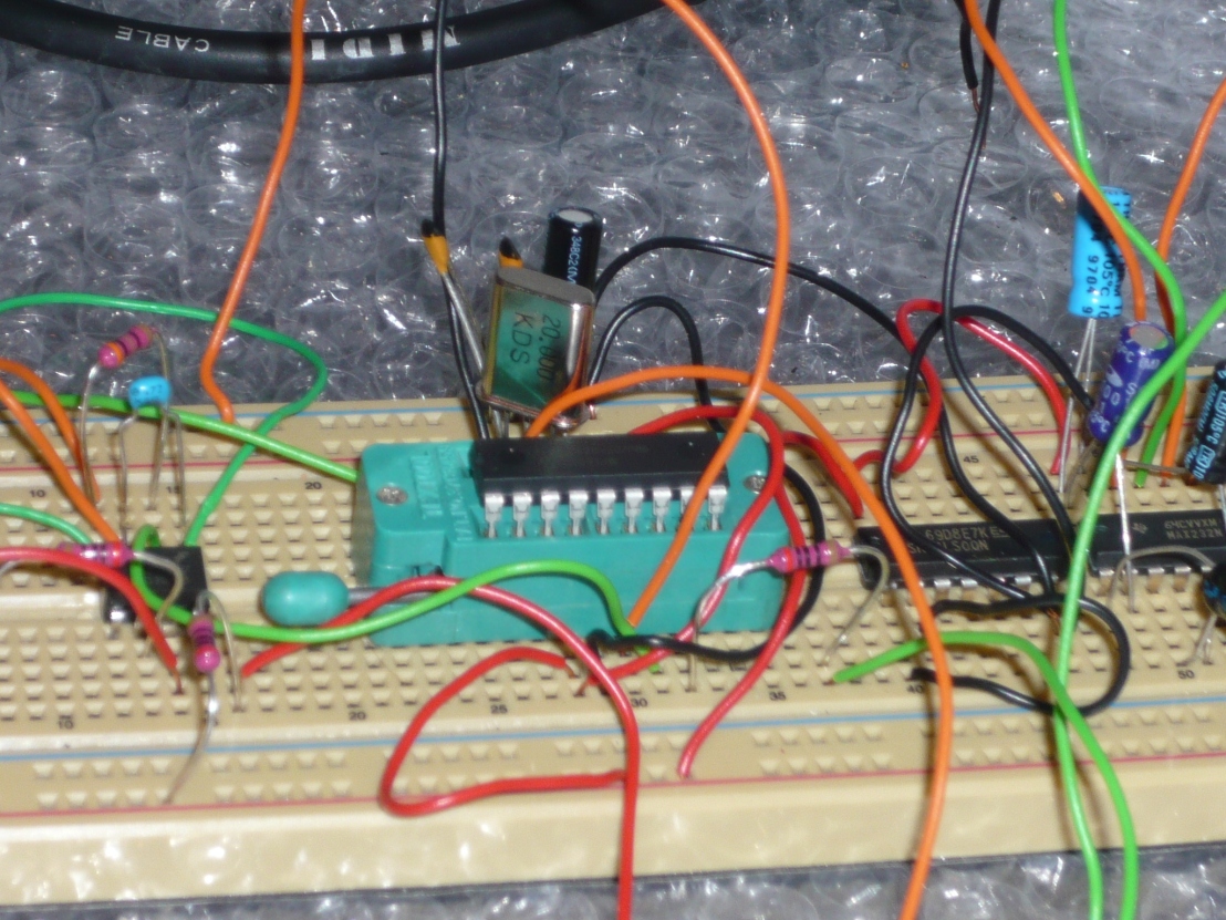
The device can easily be built on breadboard and if somebody decides to run some PCB’s off from this schematic please let me know, I might be interested to take one as well.
I created a board just to get an impression about the minimum size achievable, but it could yet be improved. Also some design rules errors are still present which have to be corrected. If you plan to reproduce this board, you should definitely consider checking the design rules!
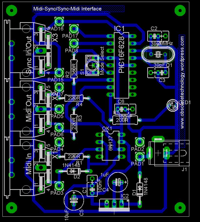
In terms of operation, there are 3 connectors on board, 1 Midi-In, 1 Midi-Out and 1 Din Sync In/Out (bidirectional Port).
Operation mode is selected with a switch and the selected mode is shown via led to the user. The led will flash 3 times long if Sync-Midi mode has been selected and 5 times short upon switching to Midi-Sync mode.
During operation, the led will blink upon each transmitted clock message/ clock signal and give feedback of correct processing.
In Sync to Midi mode, if the Sync Port is left open with nothing connected to it, the LED will start blinking and the Midi Out will send clock messages at a random rate, this because there is no Pullup/Pulldown resistor foreseen on the clock input.
You are allowed to use this code for your own NON-COMMERCIAL applications. If you re-use the code or modify it, please be so respectful to mention the original source when you publish it!
Schematics, Board, Assembly:
Download the complete project from here.
A couple more pictures from the developement:
Prototyping board setup:
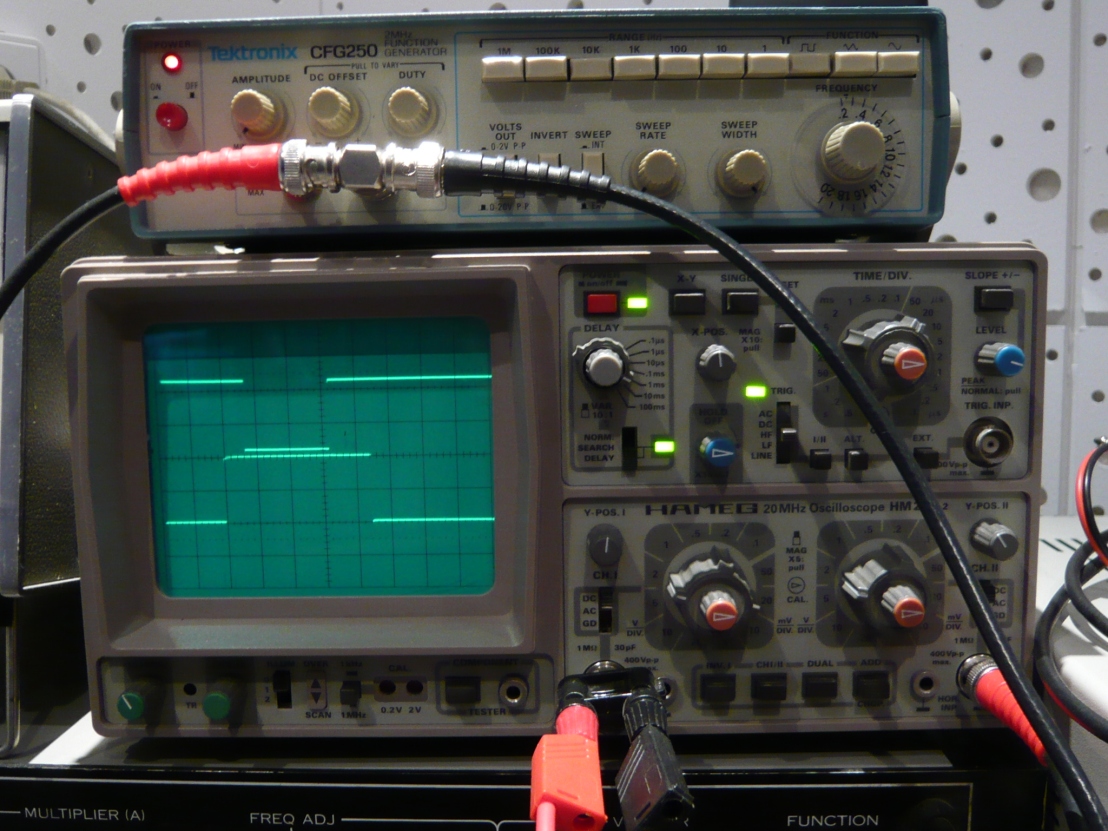
Midi Clock message on scope (F8)
Addendum:
I noticed that the PIC16F628 has got the low power programming fuse set by default, which means that if you do not explicitly turn it off, it will be set and PortB4 will not be adressable as In/Output.
That’s kind of a pitfall which could be time consuming at debugging.
So do not forget: LVP_off if you like to address PB4!
Assembler Code:
;

; -----------------------------------------------------------------------------------------------------------------------------------
;
;	2009 by Obsoletetechnology, S.Bidinger
;
;	! This code might be used for NON COMMERCIAL and DIY applications only !
;	I do share it to encourage others to do alike, so please be respectful!
;
;	If you do like this code and have used it on your apps, I would be pleased to hear so.
; 	Drop me a line under : obsoletetechnology(at)gmx.com
;
; -----------------------------------------------------------------------------------------------------------------------------------
;	Midi to Sync and Sync to Midi converter for PIC16F628 using USART
;	PIC at 20MHz  0.2us/instruction
;	DinSync Out: 24ppqn, 12ppqn, 48ppqn optional
;
;	OUTPUTS:
; 	RA0 DIN/OUT Start/Stop
; 	RA1 DIN/OUT Clock 24 ppqn
;	RA2	DIN/OUT Clock 12ppqn
;	RA3 Out Clock 48ppqn optional (commented out in code) will reduce max bpm speed of Midi-Sync conversion
;	48ppqn sync out: at Midi Sync Message: Pulse 2ms high, 2ms low, 2ms high, then low until next midi sync message, tested on Korg KPR77
;
;	RB3 Operation Indicator Out
;
;	INPUTS:
;	RA0 Start/Stop Input
;	RA1 Clock Input 24ppqn
;
;	RB0	DIN Mode select (Mode Midi-Sync or Sync-Midi)
;
;
;	16/07/2009
;	Tested, works.
;
;	22/07/2009
;	Tested ok in both directions, on TR808-TR909-X0XB0X-TR707
; 	Jitter minimal, but depending very much on Midi-Clock quality
;
;	23/07/2009
;	Added Operation Indicator Output on RB3
;	At mode switch 5 short Pulses indicate Midi-Sync operation, 3 long Pulses
;	indicate Sync Midi. OK.
;	In MS mode, Indicator is strobed on each din sync clock out.
;	In SM mode, Indicator is strobed on every midi sync message out.
;
;	Added USART overrun error clear procedure in MidiSync receive in order to avoid
;	lock up of the USART receive buffer.
;
;
;	Enjoy!
; ----------------------------------------------------------------------------------------------------------------------------------------

		LIST	p=16F628
		radix	dec
		include

		__FUSES	_HS_OSC & _LVP_OFF & _CP_OFF & _WDT_OFF & _PWRTE_ON

; Variables

		pwCount		equ 0x20		; Temporary Buffer counter1
		pwTime		equ 0x21		; Temporary Buffer counter2
		MIDI		equ 0x22		; Buffer Midi Message
		dinstat		equ	0x23		; Buffer Syncronization status
		porttemp	equ 0x24		; Buffer temporary Port Status
		dcompare	equ 0x25		; Buffer for comparison operations
		temp		equ 0x26		; temp buffer
		blink		equ 0x27		; register for blink counter

; Macros
; Macros to change memory banks
bank0	macro						;SET UP MACRO TO SWITCH TO BANK 0
		bcf	STATUS,RP0
		endm
bank1	macro						;SET UP MACRO TO SWITCH TO BANK 1
		bsf	STATUS,RP0
		endm

; Program Code
		org		0x0000				; Program reset Vector
		goto	MAIN

MAIN
; ------------------------------------------------------------------------------------------------
; Main Setup
		bank0
		clrf	PORTA				; Clear Port
		clrf	PORTB 				; Clear Port
		movlw	0x07
		movwf	CMCON           	; turn comparators off
		bcf		STATUS,DC			; set Digit Carry low

		bank1
		clrf	TRISA				; Make all PortA Output
		movlw	b'00000011'
		movwf	TRISB				; PB0 In (Mode Select),PB1 In (Rx), PB2 Out(Tx)
		movlw	0x09
		movwf	SPBRG				; Setup Baud rate generator for 31250 Baud
		bcf		TXSTA,SYNC			; Setup Asyncronous Serial Port
		bcf		TXSTA,BRGH			; BRGH = 0
		bsf		TXSTA,TXEN			; enable async transmission
		bank0
		bsf		RCSTA,SPEN
		bsf		RCSTA,CREN			; Enable reception

		call	Pulselenght			; wait for 2ms to settle

; Check Mode Select, PB0=0 -> Midi-Sync, PB0=1 -> Sync-Midi
		btfsc	PORTB,0				; Check ModeSelect State
		goto	SyncMidi

; ------------------------------------------------------------------------------------------------
MidiSync
; Port Setup Midi to Sync Mode

		bank0
		clrf	PORTA				; Clear Port
		clrf	PORTB 				; Clear Port
		movlw	0x07
		movwf	CMCON           	; turn comparators off
        bcf		STATUS,DC			; set Digit Carry low

		bank1
		movlw	b'00000000'
		movwf	TRISA				; All Port A Outputs
		movlw	b'00000011'
		movwf	TRISB				; PB0 In (Mode Select),PB1 In (Rx), PB2 Out(Tx)

		movlw	0x09
		movwf	SPBRG				; Setup Baud rate generator for 31250 Baud
		bcf		TXSTA,SYNC			; Setup Asyncronous Serial Port
		bcf		TXSTA,BRGH			; BRGH = 0
		bsf		TXSTA,TXEN			; enable async transmission

		bank0
		bsf		RCSTA,SPEN
		bsf		RCSTA,CREN			; Enable reception

; ---------------------------------------------------------------------------------------------------
		; Time waste for Startup
		call	Pulselenght
		call	Pulselenght
		call	MSBlink				; Mode Indicator Output Blink

		; Clear registers
		movf	RCREG,W				; Flush receive register
		movf	RCREG,W
		movf	RCREG,W
		clrf	MIDI
		btfsc	RCSTA,OERR			; Is overrun bit set?
		call 	ClearOverrun		; Clear OERR routine
; ---------------------------------------------------------------------------------------------------

MSLoop

Receive
		btfsc	PORTB,0				; Mode Select test
		goto	SyncMidi			; Change operation mode
		btfsc	RCSTA,OERR			; Is overrun bit set?
		call 	ClearOverrun		; Call clear OERR routine
		btfss	PIR1,RCIF			; USART reception complete bit test
		goto	Receive				; Repeat until midi byte received

		movf	RCREG,W				; Get midi data
		movwf	MIDI				; Store into midi buffer
;		call	Send				; DEBUG Mirror received Bytes Out (Midi Through) (might create some jitter on sync output
;		bcf		RCSTA,CREN			; Disable USART reception, so buffer can not fill up during data handling
									; also avoids incoming Midi Note messages messing up the sync timing, reenabling later will also clear OERR if occured
		movf	MIDI,W
		xorlw	0xF8				; Test for Midi Clock Byte
		btfsc	STATUS,Z
		goto	ClockPulse			; Clock Byte received

		movf	MIDI,W
		xorlw	0xFA				; Test for Midi Start Byte
		btfsc	STATUS,Z
		goto	StartHigh			; Start Byte received

		movf	MIDI,W
		xorlw	0xFB				; Test for Midi Continue Byte
		btfsc	STATUS,Z
		goto	StartHigh			; Continue Byte received

		movf	MIDI,W
		xorlw	0xFC				; Test for Midi Stop Byte
		btfsc	STATUS,Z
		goto	StopHigh			; Stop Byte received

;		bsf		RCSTA,CREN			; Enable USART reception again
		goto	MSLoop				; Nothing happened, begin all over
; -----------------------------------------------------------------------------------------------------
ClockPulse
		bsf		PORTA,1				; set PA1 high (24ppqn output)
		movlw	b'00000100'
		xorwf	PORTA				; Toggle PA2 for 12ppqn	and PA4 for operation indication
		bsf		PORTB,3				; Operation Indicator Output on
;		bsf		PORTA,3				; set PA3 high (48ppqn output)
		call	Pulselenght			; wait for specified time
		bcf		PORTA,1				; set PA1 low
;		bcf		PORTA,3				; set PA3 low (48ppqn output)
;		call 	Pulselenght			; wait another 2ms (48ppqn output)
;		bsf		PORTA,3				; (48ppqn output)
;		call 	Pulselenght			; (48ppqn output)
;		bcf		PORTA,3				; set PA3 low (48ppqn output)
		bcf		PORTB,3				; Operation Indicator off
;		bsf		RCSTA,CREN			; Enable USART reception again
		goto	MSLoop				; Wait for next midi byte

StartHigh
		bsf		PORTA,0				; Set PA0 high
;		bsf		RCSTA,CREN			; Enable USART reception again
		goto	MSLoop				; Wait for next midi byte

StopHigh
		bcf		PORTA,0				; Set PA0 low
		call	ClearMem			; Clear registers
;		bsf		RCSTA,CREN			; Enable USART reception again
		goto	MSLoop				; Wait for next midi byte
; ------------------------------------------------------------------------------------------------------
SyncMidi
; Port Setup for Sync to Midi Operation
		bank0
		clrf	PORTA				; Clear Port
		clrf	PORTB 				; Clear Port
		movlw	0x07
		movwf	CMCON           	; turn comparators off
        bcf		STATUS,DC			; set Digit Carry low

		bank1
		movlw	b'00000011'			; Clock Input PA1, Start/Stop input PA0
		movwf	TRISA
		movlw	b'00000011'			; PB0 In (Mode Select),PB1 In (Rx), PB2 Out(Tx)
		movwf	TRISB				;

		movlw	0x09
		movwf	SPBRG				; Setup Baud rate generator for 31250 Baud
		bcf		TXSTA,SYNC			; Setup Asyncronous Serial Port
		bcf		TXSTA,BRGH			; BRGH = 0
		bsf		TXSTA,TXEN			; enable async transmission

		bank0
		bsf		RCSTA,SPEN
		bsf		RCSTA,CREN			; Enable reception

		clrf	MIDI				; Clear Midi Buffer
		clrf	dinstat				; Clear Buffer Syncronization status
		clrf	porttemp			; Clear Buffer temporary Port Status
		clrf	dcompare			; Clear Buffer for comparison operation
; Wait to settle
		call	Pulselenght			; Wait for 4ms to settle
		call    Pulselenght
		call	SMBlink				; Mode indicator Output blink
; ------------------------------------------------------------------------------------------------------
; Sync to Midi Loop
SMLoop
		movfw	PORTA
		movwf	porttemp			; save port status temporary, in case status changes during operation

		movfw	dinstat				; put previous digital input port status into w
		movwf	dcompare			; move digital in status to coparison register

; test if change on PA0 (Start/Stop)occured
		movlw	b'00000001'
		andwf	dcompare			; mask all bits except bit 0 (start/stop)
		movlw	b'00000001'
		andwf	porttemp,W			; mask all bits except bit 0, into W register
		subwf	dcompare			; compare bit4 of both registers
		btfss	STATUS,Z			; if nothing changed, skip next instruction
		goto	STARTSET			; either Start or stop occured, send midi message

; test if change on PA1 (clock) occured (only positive change)
		btfss	porttemp,1
		goto 	ENDPOLL				; do only if Clock high

		movfw	dinstat				; put previous digital input port status into w
		movwf	dcompare			; move digital in status to coparison register

		movlw	b'00000010'
		andwf	dcompare			; mask all bits except bit 1 (clock)
		movlw	b'00000010'
		andwf	porttemp,W			; mask all bits except bit 1, into W register
		subwf	dcompare			; compare bit 1 of both registers
		btfss	STATUS,Z			; if nothing changed, skip next instruction
		goto	CLOCKSET			; Clock high occured, send midi message

		goto	ENDPOLL				; nothing happened

; Send Midi messages
CLOCKSET
		movlw	0xF8			; Midi Clock Byte
		movwf	MIDI			; Load midi byte into register
		call	Send			; Call Midi send routine
		movlw	b'00001000'
		xorwf	PORTB			; toggle operation indicator output
		goto	ENDPOLL			; 26us until clock command goes out (0.026ms)
								; at 24ppqn and 120 bpm we have 1 pulse each 20833us

STARTSET
		btfsc	porttemp,0		; Start or Stop?
		goto	Startbyte
Stopbyte
		movlw	0xFC			; Midi Stop Byte
		movwf	MIDI			;
		call	Send			; Goto Midi send routine
		goto	ENDPOLL

Startbyte
		movlw	0xFA			; Midi Start Byte
		movwf	MIDI			;
		call	Send			; Goto Midi send routine
		goto	ENDPOLL

ENDPOLL
		movfw	porttemp
		movwf	dinstat			; store previous port status
		btfss	PORTB,0			; ModeSelect test
		goto 	MidiSync		; MidiSync Mode selected
		goto	SMLoop 			; Repeat

; ------------------------------------------------------------------------------------------------------
; -----------------------------------------------------------------------------------------------------------
; SUBROUTINES
; Serial Data receive routine
;Receive
;		btfsc	PORTB,0				; Mode Select test
;		goto	SyncMidi
;
;		btfss	PIR1,RCIF			; Reception Complete bit test
;		goto	Receive				; Repeat until midi byte received
;
;		movf	RCREG,W				; Get midi data
;		movwf	MIDI				; Store into midi buffer
;
;		return

; Serial data send routine
Send
		movfw	MIDI
		movwf	TXREG				; Load data to be transmitted
		bank1
Transmit
		btfss	TXSTA,TRMT			; 1 if transmission finished
		goto	Transmit
		bank0
		return

; Clear registers
ClearMem
		movf	RCREG,W				; Flush receive register
		movf	RCREG,W
		movf	RCREG,W
		clrf	MIDI
		return

; Clear USART Overrun Error
ClearOverrun
		bcf		RCSTA,CREN			; Disable USART receive
		bsf		RCSTA,CREN			; Enable USART receive
									; This clears OERR!
		movf	RCREG,W				; Flush receive register
		movf	RCREG,W
		movf	RCREG,W
		clrf	MIDI
		return

; Wait determined Pulselenght
Pulselenght
; Clock Sync Pulsewidth, 2.007ms
		movlw	0x0D				; (1)
		movwf	pwTime				; (1)
DLoop1
		movlw	0xFF				; (1)
		movwf	pwCount				; (1)
DLoop2
		decfsz	pwCount				; (1\2) (256*3)+ 3 = 771*0.2 = 154.2us
		goto	DLoop2				; (2)

		decfsz	pwTime				; (1\2)	(13*154.2)+3 = 	2007.6us
		goto	DLoop1				; (2)

		return

; Blink PB3 5 times short
MSBlink
		movlw	0x05
		movwf	blink				; do 5 times
blinksh
		bsf		PORTB,3				; turn on PA4
		call	Waitshort
		bcf		PORTB,3				; turn off PA4
		call	Waitshort
		decfsz	blink				; done 5 times?
		goto	blinksh
		return

; Blink PB3 3 times long
SMBlink
		movlw	0x03
		movwf	blink				; do 3 times
blinklng
		bsf		PORTB,3				; turn on PA4
		call	Waitlong
		bcf		PORTB,3				; turn off PA4
		call	Waitlong
		decfsz	blink				; done 3 times?
		goto	blinklng
		return

; Wait approx 500ms
Waitlong
		movlw	0x08
		movwf	temp
WLoop1
		movlw	0xFF				; (1)
		movwf	pwTime				; (1)
WLoop2
		movlw	0xFF				; (1)
		movwf	pwCount				; (1)
WLoop3
		decfsz	pwCount				; (1\2) (256*3)+ 3 = 771*0.2 = 154.2us
		goto	WLoop3				; (2)

		decfsz	pwTime				; (1\2)	(256*154.2)+3 = 39424us
		goto	WLoop2				; (2)

		decfsz	temp				; 14* 39424us = 551936us
		goto	WLoop1
		return

; Wait for approx. 250ms
Waitshort
		movlw	0x03
		movwf	temp
WsLoop1
		movlw	0xFF				; (1)
		movwf	pwTime				; (1)
WsLoop2
		movlw	0xFF				; (1)
		movwf	pwCount				; (1)
WsLoop3
		decfsz	pwCount				; (1\2) (256*3)+ 3 = 771*0.2 = 154.2us
		goto	WsLoop3				; (2)

		decfsz	pwTime				; (1\2)	(256*154.2)+3 = 39424us
		goto	WsLoop2				; (2)

		decfsz	temp				; 7* 39424us = 275968us
		goto	WsLoop1
		return

		end
