Purpose
Low cost CV-Gate to Midi converter allowing to convert analog CV-Gate and CV signals into Midi Note On/Off and Midi CC messages.
The circuit is mainly based on an analog to digital converter with a midi output. It is intended to be used with analog sequencers, modular systems or signal generators, wherever a conversion of analog signals into Midi messages is required.
The module provides 3 CV-Gate input channels and can be configured to handle these 3 CV-Gate input channels as monophonic or as polyphonic input sources, either generating 3 independent midi Note On/Off messages with different midi channels, or in poly mode, generating note messages on one common midi channel.
Additional to the CV-Gate inputs, the module provides 2 more input channels for CV signals, which are converted into Midi CC messages.
The module has been designed for lowest cost, thus mainly making use of one single PIC microcontroller and few other components. Analog input buffers have been left out on purpose in order to keep part counts low. S
Since the unit is only running on a unipolar (positive) power supply, the actual input voltage range covers the positive voltages alone. In the case that a bipolar input voltage range would be required, an additional input buffer offsetting the measured signal into the positive range would have to be added.
Features
- 10 bit AD resolution (using Pic internal AD converter)
- 250Hz sampling rate on CV CC inputs.
- Interrupt driven sampling of the CV inputs on status change of the gate inputs.
- 10bit resolution for CC Midi out ( split over 2 midi CC messages) possible. (disabled in current code)
- CV-Gate Input internal conversion to V/Oct range midi note messages (7bit)
- 5V or 10V CV input range for V/Oct conversion.
- Mono/Polyphonic CV-Gate mode selectable.
- Midi channel configurable.
- Midi Channel and Mono/Poly Mode stored in non volatile memory.
- Analog input protection.
- Low cost.
- Low part count.
- Simple design, easy for DIY building.
Operation
- Button hold at power-on will toggle the mono/poly mode.
- Button press at runtime will increment the current midi channel by one. The midi channel is indicated by the number of times the LED flashes after button press. Once midi channel 16 has been reached, the system will turn around to channel 1 at the next button press.
- In mono mode, the selected midi channel represents the midi base channel. The midi channels for the 2 other inputs are automatically assigned to base channel+1 respectively to base channel+2.
- The midi CC messages are always sent on the base midi channel.
- The led will blink at power up in order to show that the module is running.
Also, the led flashes each time a midi message is sent, allowing to verify the function of the module.
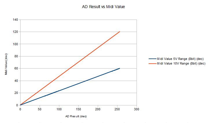
AD Conversion Value vs Midi Note Value Chart
The unit can handle 2 input voltage ranges, either 5V or 10V on the CV inputs. The input mode is configured via the input range jumper. For 10V mode, the CV input circuit requires to have the input voltage divider in place, in order to provide the correct input voltage to the AD converter as well as to protect the AD inputs of the microcontroller. The AD range conversion calculation is implemented with a lookup table correlating the measured AD results to the Midi Note values.
5V input mode covers an octave range of 5 octaves, 10V allows a 10 octave range.

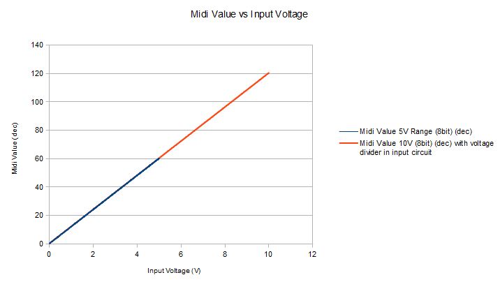
Control Voltage Input vs Midi Result Value
This chart shows the extended measurement range of the converter in 10V mode.

Remember, 10 Volt mode requires to have the voltage divider setup in the CV Inputs.
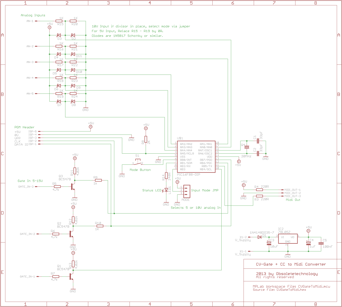
Schematic:

Circuit description:
The heart of the system is a PIC16F88 microcontroller running at 20MHz. The analog inputs for control voltage input are passed through a simple voltage divider in order to allow a max CV input of 10V. Alternatively, the input resistor can be left out which results in a maximum input voltage of 5V. The jumper JP1 configures the CV conversion for either 5 or 10V input mode.
A voltage clamp using Schottky diodes protects the microcontroller’s analog inputs from overvoltage.
The gate inputs are buffered with a simple transistor buffer which allows gate voltages in a range of 3-15V.
The circuit provides also a header for in-circuit-programming and a status LED output.
The mode button is used for midi channel selection as well as for mono/poly mode switching.
Code/Firmware
The firmware is written in C for HitechC compiler v9.83 running in light (free) mode.
There are 2 interrupts which run the main tasks, one servicing the IO level change event on the gate input pins, generating the note on/off midi messages and a second interrupt configured for the timer event which defines the additional CV input scan rate responsible for generating the CC midi messages.
Upon interrupt for gate input change (gate input status has changed), the AD conversion for the corresponding CV channel is started. Once the AD conversion result is available, the assigned midi note is looked up from the lookup table based on the ad conversion value truncated to 8 bit resolution. The table lookup also transforms the now truncated 8bit AD result into a 7bit midi note. This also means that there is some note quantization going on for in-between note values.
From the gate polarity it is deduced whether a note on or off message has to be sent. Then, the midi note send function is called which outputs the 3 midi bytes on the usart tx pin. Depending on whether the system is in monophonic or polyphonic mode, either the midi channel is linked to the gate number which has been triggered (with the midi root channel as starting point for the first gate channel) or, in poly-mode, always using the same root midi channel.
Upon timer interrupt, the AD conversion for the additional CV inputs is started, resulting in a midi CC message to be sent. Since the AD converter has a resolution of 10 bits, the value is truncated to 7bits resolution. The Midi channel used for transmission of the CC midi messages is always the midi root channel, meaning the channel learned in the midi channel setup procedure.
The other parts of the code are mainly for peripheral setup and configuration button logic. This is run from the main loop as well as some eeprom handling for storage and retrieval of the configuration parameters.
CV-Midi Note Lookup Tables can be found in the project documents:
YOU ARE ALLOWED TO USE THIS CODE FOR YOUR OWN NON-COMMERCIAL APPLICATIONS. IF YOU RE-USE THE CODE OR MODIFY IT, PLEASE BE SO RESPECTFUL TO MENTION THE ORIGINAL SOURCE WHEN PUBLISHING.
THIS CODE AND INFORMATION ARE PROVIDED “AS IS” WITHOUT WARRANTY OF ANY
KIND, EITHER EXPRESSED OR IMPLIED, INCLUDING BUT NOT LIMITED TO THE
IMPLIED WARRANTIES OF MERCHANTABILITY AND/OR FITNESS FOR A
PARTICULAR PURPOSE.
