PIC16F628A based Midi to CV converter with an additional CC output.
Here is my version of an Midi/CV converter, a low cost, low part count design with an additional CC output, 8 bit resolution and integrated logarithmic scale conversion for V/Hz controlled synthesizers. Code and schematics download can be found at the end of this document.
Update 01/10/2011:
Updated firmware to v1_2 for better handling of CC Controller messages. See below for the new features.
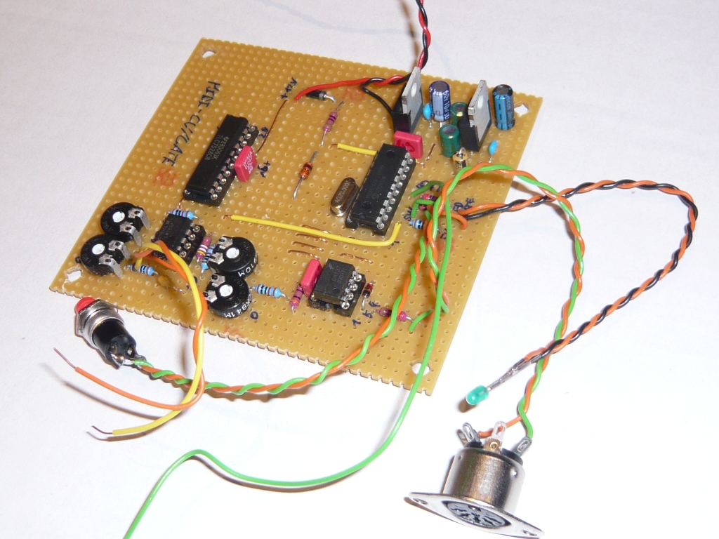
The key features:
- Low cost, part costs below 20E. ( actually with the power supply it is more expensive)
- 8 bit resolution.
- Midi Channel learn function by button press.
- Midi Channel saved to EEprom and loaded on next startup.
- Midi CC Channel learn function by button press. (new)
- Midi CC Channel saved to EEprom and loaded on next startup. (new)
- Midi CC Controller number learn. (new)
- Midi CC Controller number saved to EEprom and loaded on next startup. (new)
- Linear and Logarithmic CV curve implemented on microcontroller as a lookup table
- CV mode saved to EEprom and loaded at next startup
- Gate off via either note-off command(8xh) or by note-on with velocity zero
- Linear mode range: 8 octaves
- Logarithmic mode range: 3.octaves
- CC Controller parameter out on second DAC output
- Positive supply voltage only, no bipolar power supply needed
Purpose
The purpose of a CV/gate converter is to transform incoming midi-note messages into control voltage for monophonic synthesizers featuring a CV/gate input, like Minimoog, Roland System 100, SH101, Korg Monopoly etc. Furthermore, a logarithmic lookup table has been implemented for those synthesizers which require a Voltage/Hz scaling rather than linear scale as a control voltage. CC control messages are decoded as well and put out on the second output of the DA converter.
Operation
During normal operation, a new midi channel can be learned by pushing the Learn/Mode button once. The indicator LED will light up and remain lit until a midi note or Control CC has been received.
Midi Messages: (Note on: 0x9m, Note off: 0x8m, CC: 0xEm) where m is midi Channel.
The channel of that incoming midi note will then be stored in EEprom memory. The LED will strobe for 1 second to indicate the storing operation.
Same function for CC Messages, CC midi channel will be stored in EEprom memory as well as the CC controller identifier number. (new)
Note that the midi channel for CC Messages is allowed to differ from the Key On/Off midi channel. This allows to receive Key and CC messages from two separate sources for both control and key On/Off. (new)
This also means that in order to configure the device, the learn function has to be operated twice, once for Key and once for CC messages. (new)
At next power cycle, the last stored Midi channel will be retrieved from the EEprom memory. Successful loading of the midi channel will be shown by a LED strobe at startup.
Logarithmic CV scale mode also known as V/Hz mode (as can be found on KORG MS10, MS20) is accessed by holding the Learn/Mode button pressed at power up. This will toggle the CV mode. At button release, the LED will blink 4 times to show that we’re in V/Hz mode or blink 2 times long to display V/Oct mode. The CV mode is stored into EEprom memory as well and will be loaded at startup if no button is held.
Please note that the EEprom values after programming the microcontroller will be FF, which is an invalid Midi Channel and invalid CV mode. Therefore the channels for CC and Key On/Off have to be learned at the first startup, as well as the CV mode which needs to be stored once.
You will notice that for the logarithmic mode, some rounding to the midi values had to be done to fit the 8bit max resolution of the DAC. This has as a side-effect that the range in log mode is severely restricted (to 3.5 octaves) and the precision is not too good, especially on the lower notes. I would therefore not recommend this mode if very accurate tuning is required, but for general playing with these kinds of synths it should be good enough.
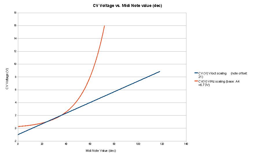
The lookup table calculation can be seen in the table below, the logarithmic values have been calculated based on the midi values whith A4 as reference note. Then some offset has been added to achieve the required voltage levels, which means:
C1:1V; C2:2V; C3:4V; C5:8V and so on, but limited by the maximum output voltage of the converter.
The lookup-table calculation can be found here.
Here a plot of the required voltage levels versus midi note values for both log and linear modes:
As a comparison, I drew a plot plot of the CV output voltage from my converter versus a Kenton Pro-Solo as reference:
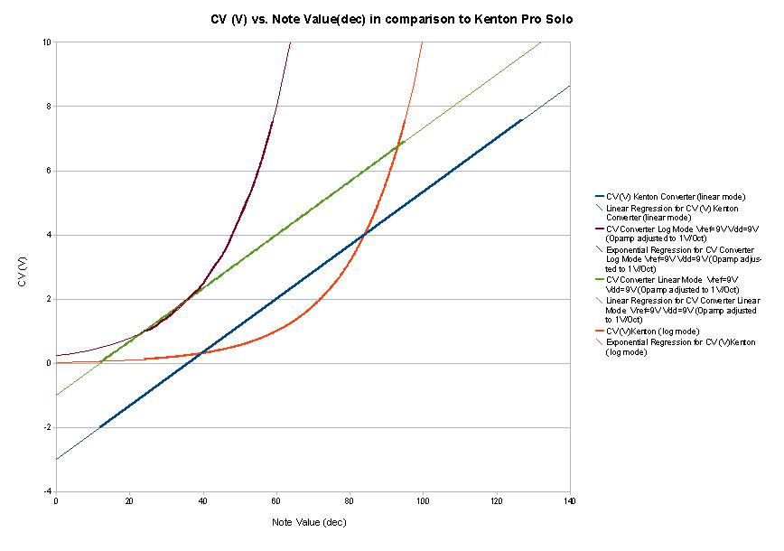
It is to be noticed that the converters, except for the offset, perform the same and produce the same voltage levels for a given midi note value.
The Kenton converter has the ability of a higher voltage swing and voltage even goes negative, which my design cannot achieve with the chosen power supply.
(update : 03/04/2012):
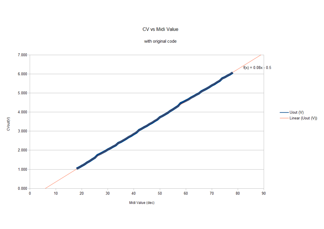
I have made a detailed measurement of the CV output voltage vs Midi note value and discovered a repeating non-linearity on the output of the DA Converter
Following picture shows the behaviour quite clearly, every 8th value is out of line:
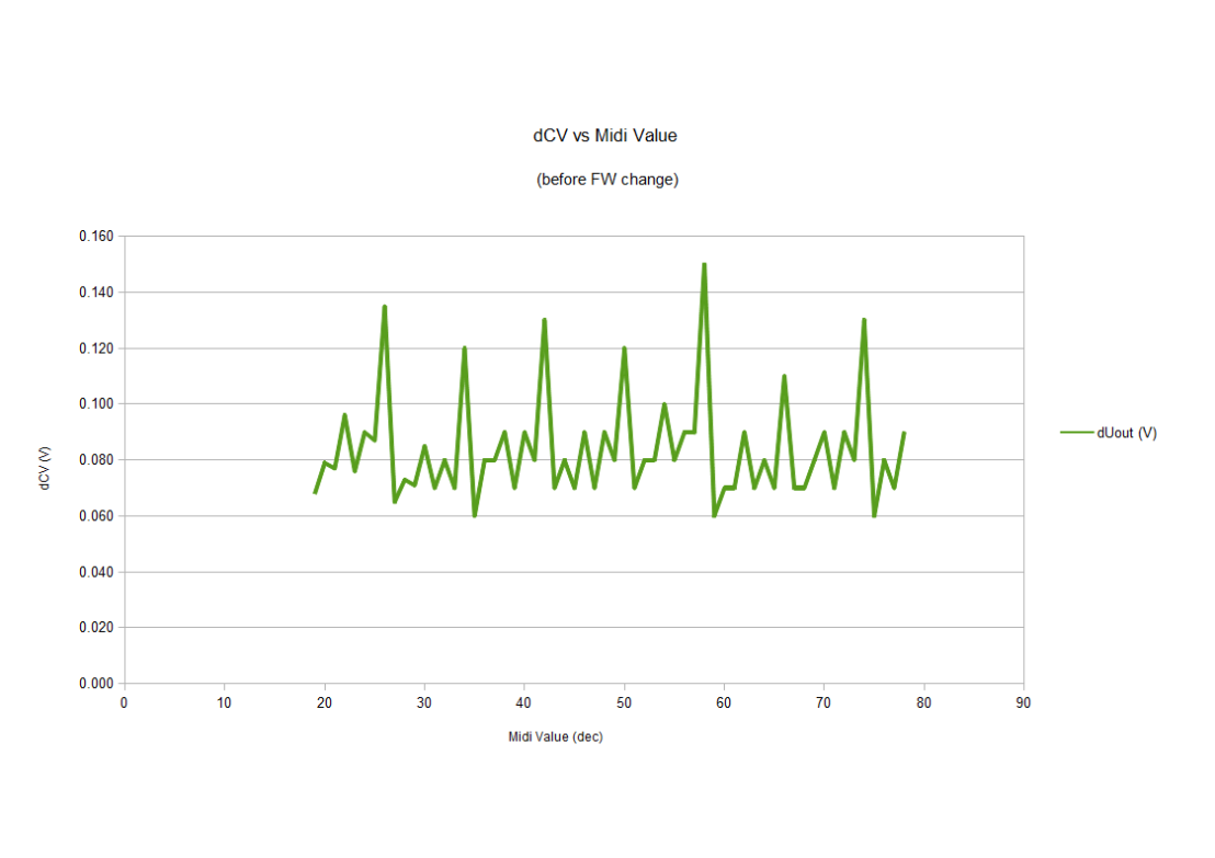
The da-converter output voltage change per midi note value (ideally, this should be represented by a flat line with 0.083V between each step):
After verifying the digital outputs on the uC to the DA in order to make sure the data transmitted to the DA converter is correct (which it is) I can only conclude that the non-linearity’s origin is either the DA converter itself or the way the DA is used here (in voltage mode). The DA converter’s datasheet states an LSB error of 1bit in voltage mode, which would sum up in this case to Vref/2^8 = 0.035V. This value is already larger than one third of a note which is 0.0833V, so quite a lot and too much for a correct note tracking on a synthesizer.
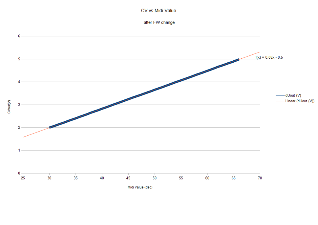
In order to improve the situation, I have modified the firmware and shifted the standard 7bit midi note value one position left, which actually doubles the value. Now, using a voltage reference of 4.7V instead of 9.1V the error of the DA converter gets reduced by half it’s amount. The max error voltage on the DA converter would therefore become: 4.7V/256=0.018V
Here the CV vs Note value plot after firmware modification:
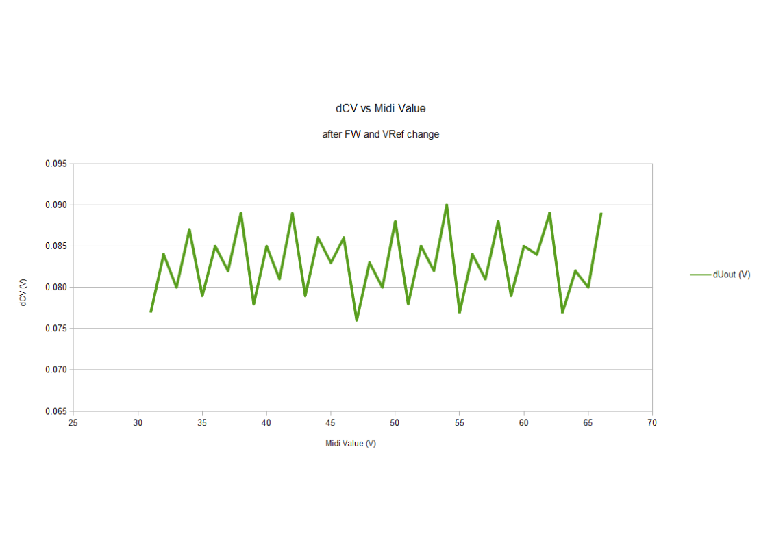
The da-converter output voltage change per midi note value (ideally, this should be represented by a flat line with 0.083V between each step):
Now we can observe an improvement of the linearity although it has not yet become totally satisfactory. In order to improve the linearity even more, it would be possible to use a 12bit DA converter and connect only the 7 MSB inputs from the uC, leaving the remaining 4 LSB inputs to 0. Here, with an error of 1LSB on the converter, the error voltage would be in the range of max Uref/2^12 = 4.7/4096=0.0011V
Unfortunately, the logarithmic mode for the uC had to be removed for that firmware update, since it relied on a 7bit midi message and an 8bit lookup table on the controller. All other functions and CC messages stay unchanged.
Parts & Schematics
The converter is build around a PIC16F628A microcontroller and a TLC7528 dual 8bit DAC .
The other parts are an operational amplifier for DAC buffer, voltage gain and offset of the output voltages and an optocoupler required for midi input as well as 2 power regulators for the power supply and a z-diode as a reference voltage generator for the DA converter. Part costs are quite low, it should be possible to build this for around 20E, depending on how fancy you get.
I initially developed this interface for PIC16F628 microcontrollers which in the meantime has been replaced by the PIC 16F628A. This uC is pin compatible with the previous 16F628 and the circuit works the same for both micros.
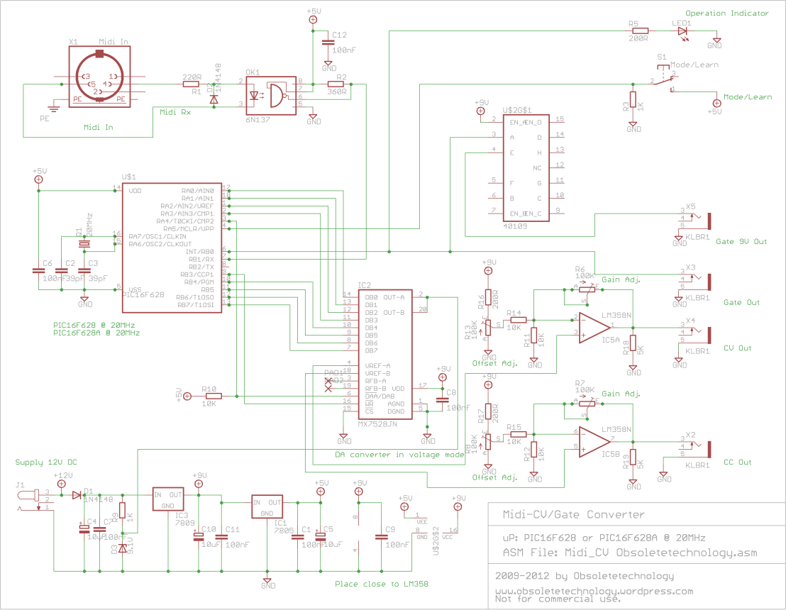
Circuit design
With low cost in mind, the circuit has been designed for single supply rail.
Supply voltage is 12V followed by two power converters, once 9V for the DA converter/Opamp and once 5V for the microcontroller and optocoupler. A diode protects the circuit from reverse polarity and the 9.1V reference voltage is generated with the help of a resistor/Z-diode combination in parallel to V supply.
UPDATE: 03/04/2012:
For the sake of DA converter linearity improvement, the voltage reference z-diode has been changed to 4.7V and can now be placed after the 5V regulator.
Midi Input according to the midi specifications over an optocoupler towards serial input of microcontroller.
The DA converter is used in voltage mode, thus the reference voltage is fed into the output of the DA and the signal output is available on REFA respectively REFB. (see TLC datasheet for more info about voltage mode).
The LM 358 serves as buffer for the DA converter as well as gain and offset for the two output signals. The opamp is wired in non-inverting mode and on single supply rail. Opamps powered on a single rail usually have a hard time to reach the lower supply rail voltage (here 0V), therefore special care has to be taken when designing single supply circuits. Here in this case, the feedback and inverting input resistor values had to be chosen quite high in order to achieve a good voltage swing towards the lower supply rail. To increase the low power rail capability even more, a load resistor has been added to the opamp outputs. In this configuration it is possible to reach 0.05V as lowest voltage output without an additional load connected, which is sufficient for the application.
Some equipment (like Roland System 100) require a gate voltage level higher than the typical TTL (5V) level as trigger input. Therefore I added to my Midi converter a CD40109 CMOS low to high level shifter which raises the level of the gate signal to 9V. On my System 100 this works very well. The second schematic in the downloadable project folder shows this addition.
Calibration procedure:
The opamp output has to be adjusted for 1V/octave. In order to do so, hook up a voltmeter to one of the channel outputs. Then adjust both potentiometers gain and offset to mid position. Connect midi input to keyboard, do channel setup and make sure the microcontroller is in linear mode
Play note C1 and adjust offset to 1V. Play note C4 and adjust gain to 4V. Then, play C1 and re-adjust offset to 1V. Play C4, adjust gain to 4V. Repeat this operation until precision is sufficiently accurate.
Same procedure is valid for calibration of the CC output, a hex value 0x24 should produce 2V, an hex value 0x54 should produce 6V. Repeat operation as described above until values are sufficiently accurate.
Some details:
PortA 4 on the Pic16F628A is of open drain type, which means that this output can only drain current. In order to use it as a voltage output, a pullup resistor has to be put in line to VCC.
PortA 5 is input only, and can be accessed by turning MCLRE off in the PIC’s fuse settings
PortB4 is by default used for low voltage programming, in order to use it as an In/Output, LVP must be set to off in the fuse settings.
In my case, I found that it is not possible to use PortB2 as an output when in USART mode, even if TXA is disabled. Strangely, MPLab’s simulator is able to do exactly that. But it is anyway known that the simulator is not 100% accurate if it comes to USART simulation.
That’s the reason why the Indicator LED and Gate Output now share one port.
Update (12/09/2010)
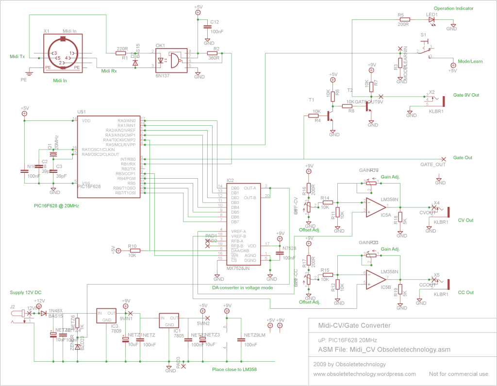
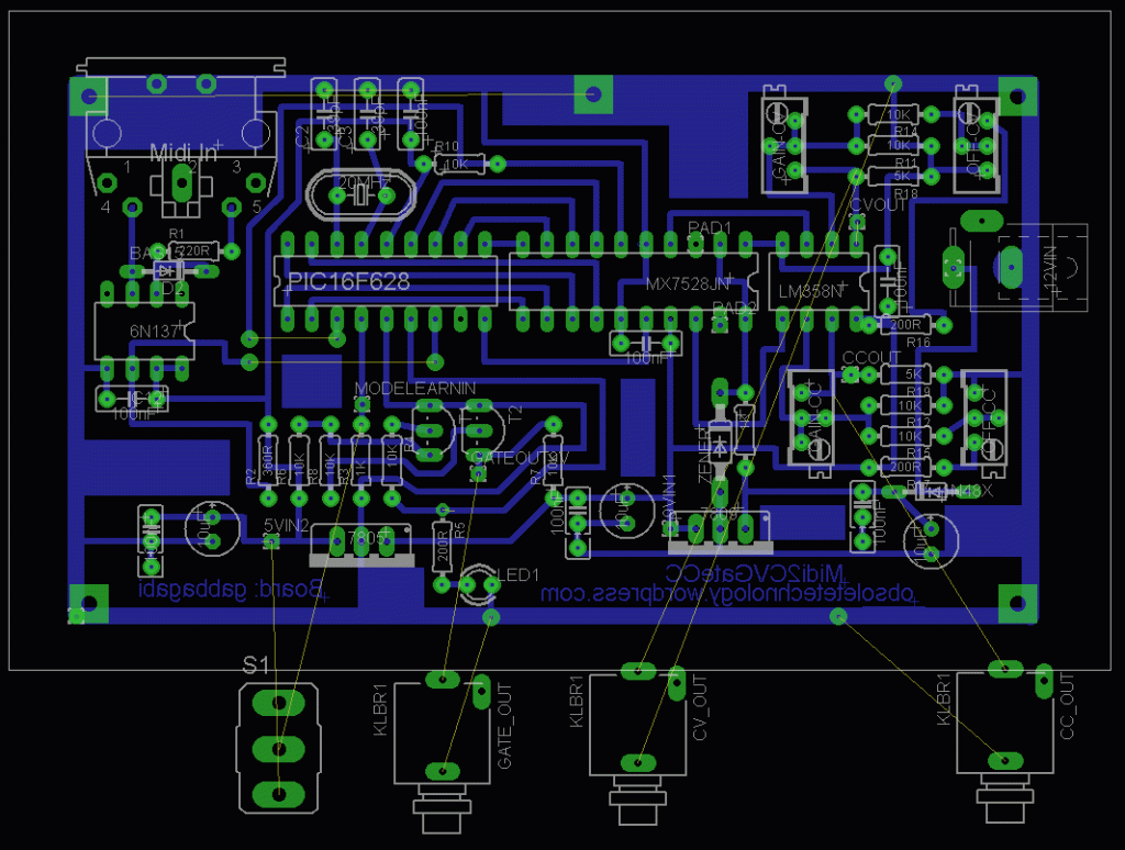
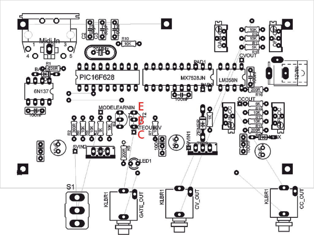
<Gabbagabi> has created a really nice PCB for my project, he substituted the CD40109 level shifter with a transistor line driver, which will reduce the production cost even more. I added his board and schematic to the Project download folder. Both transistors are BC547.
Here Gabbagabi’s version of the schematic and board:
And the corresponding board layout:
Part placement:
(update 04/04/2012):
The zip file holds the firmware and schematics for the original project, the modified project with linearity improvement compiled for both PIC16F628 and PIC 16F628A as well as the circuit layout for Gabbagabi’s pcb design.
You are allowed to use this code for your own NON-COMMERCIAL applications. If you re-use the code or modify it, please be so respectful to mention the original source when you publish it!

