Yet another Ursa Major Space Station has arrived for repair. Symptoms described were mangled and noisy audio and no audible reverb effect.
As usual, I started the diagnosis by checking for any short circuits on the various supply buses, where I immediately spotted a short-circuited tantalum capacitor in the +15V supply. After replacing that one and testing once again for shorts I powered the unit with mains supply, where as a surprise I was greeted by some magic blue smoke emanating from the transformer and later a melting primary fuse. Well, that had not been part of the initial fault description… So it seems like the transformer will have to be replaced as well.


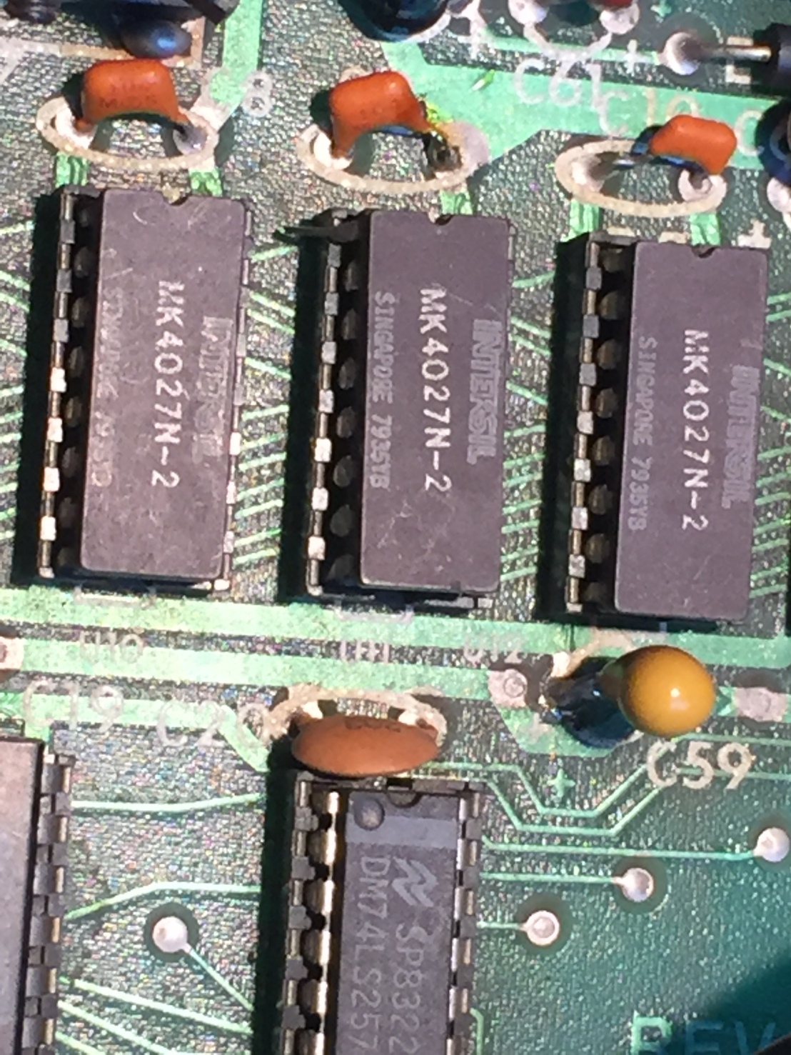
To continue diagnosis, I then used an external power supply as power source and went on with my analysis. Using the very well written service manual and with the unit in service mode (Jumpers in the forseen 8 pin socket), I traced the various timing and control signals where I determined a problem with one of the memory IC’s. Taking a closer look at the memories I was able to find that fault with my bare eye: one of the chips was badly inserted in it’s socket, leaving the memory chip’s signal levels afloat. I can only explain this as the result of a previous unsuccessful repair attempt.
With the memory chip now inserted properly I went on and hooked up a signal generator to the audio input in order to trace the signal path and test if the audio would now be correctly processed. Unfortunately, only the upper half-wave of the fed-in sine wave would be processed, which meant that there was another fault still. After some time spent on consulting the schematics and some probing with the oscilloscope I determined a faulty CMOS switch on the ADA board. Once that part had been exchanged, the SST-282 was operating properly again.


Next, I went on and replaced some wacky looking electrolytic capacitors as well as all tantalum’s in the power supply, just to make sure that the unit will not shorten again in near future.
Once that was done I proceeded to replace the faulty power transformer. The original transformer had two separate windings in order to provide +-8Vac and +-17Vac. Unfortunately I was not able to find a similar Transformer at a reasonable price, therefore I opted to replace the transformer by two separate transformers of the required output voltage. At installation, I aligned them properly so it does not look too different from the original installation.


During the waiting time for the transformers to arrive, I took the opportunity to read out the PROM images from the three programmable ROM’s on board. These PROM’s store the memory look-up tables for the different reverberation algorithms. The link to that project can be found here.


After that, the unit was reassembled, given a good clean and then sent back to the lucky owner.


