
This device allows the filtering of midi messages on the midi bus. The unit provides a wide variety of configurations while only requiring a very basic user interface.
The unit is designed as a low cost/low part count device targeted at diy-building and is based on a pic16f1829 microcontroller running at 32Mhz.
Utilization examples:
- Pass only midi note on/off events.
- Let midi sync only through on one single channel.
- Remove everything except CC messages.
- Parse Program Change messages.
Utilization Notes
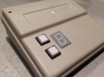
The configuration setup of the Midi Filter Tool is a bit reminiscent of early digital watches with the typical step through parameter interface by the use of only 2 buttons.
The device has 2 configuration states, first is the ‘MODE’ state, second is the ‘TOGGLE’ state.
Pressing the MODE button will iterate through three configuration parameters:
0. Filter Mode Selection:
Filter mode selection configures how the selected midi channel should be applied on the filter. There are 3 possibilities counting from 0 to 2 at every pressing of the toggle button. The 3 possibilities are: 0:All Channels(Omni), 1:Single Channel, 2:All but one channel
1. Filter Message Filter Setup:
The midi message filter setup determines which of the incoming midi messages should be passed through to the midi output of the device and which should be omitted. The active selection is displayed on the 7 segment displayed by a continuously lit segment. As an example, if all messages were to be passed through, all segments on the display would be lit.
Pressing the toggle button will move through setup bits.
The selected bit is shown by blinking the segment Led. Pressing Mode will set/reset the selected bit
Bit sequence (corresponding segment in brackets):
0(A):Midi Clock
1(B):NoteOff
2(C):NoteOn
3(D):Aftertouch
4(E):CC
5(F):PatchChange
6(G):ChannelPressure
7(H):PitchBend
To exit filter setup mode: Hold Toggle and then press Mode to in order to return to ‘Mode’ state.
2. Midi Channel Select: Active midi channel
The selected channel defines on which midi channel the midi filter is active on, except for omni mode, where it is active on all channels. Pressing the toggle button will iterate through the 16 available midi channels, displayed here in hexadecimal, since we only have one 7 segment display. So, midi channel 1 is represented by a ‘0’ on the display, channel 16 by ‘F’.
Storing the configuration:
In order to store the configuration to EEprom: Hold Mode, Press Toggle – Will show on 7 Segment
Pressing the TOGGLE button will increment or toggle the parameter selected by the MODE button.
The state is shown via the digital point on the 7 Segment Display: When DP is lit, unit is in ‘MODE’ state, unlit means ‘TOGGLE’ state.
Known and identified midi messages:
Midi  Command Meaning     # parameters  param 1       param 2
0x80  Note-off            2             key           velocity
0x90  Note-on             2             key           velocity
0xA0  Aftertouch          2             key           touch
0xB0  Continuous controller 2           controller #  controller value
0xC0  Patch change        2             instrument #
0xD0  Channel Pressure    1             pressure
0xE0  Pitch bend          2             lsb (7 bits)  msb (7 bits)
0xF0  (non-musical commands)
0xF8  Midi Clock24 ppqn   0
All midi message related data from midi.org
Led Display Assignment
The leds are assigned to midi messages as depicted in the picture below. This summary can be used as short user manual by sticking it to the device’s housing.

Circuit Diagram

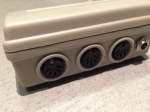
The circuit is a very simple Midi-In/Midi-Out/Midi-Through setup. The midi input is decoupled via optocoupler as per midi specification. The PIC16F1829 microcontroller is running on its internal oscillator, hence no external crystal is required for the operation. A 5V power regulator has been added, should the unit need to be driven by a higher voltage DC source.
Board Layout

Since I did not want to mess around with prototyping boards this time, I had a nice PCB manufactured at OSH Park.
The PCB’s are of an amazing quality and at a very fair price, highly recommendable!
Firmware
The project has been written for a PIC16F1829 micro using SDCC v3.2 as compiler.
The midi input is handled through an interrupt on the USART port, which then fills into a FIFO buffer. The main loop continuously processes the fifo buffer and compares the incoming data with the setup filter parameters, which then decides whether the data belongs to one of the midi parameters to be blocked or to be let through to the output.
Care has been taken to have the most time critical parameters processed first (like midi sync and note on/off), so they show minimum latency at the output port, less time critical parameters like program changes are handled last.
The main loop is also handling the user interface, calling the button read and menu functions.
Project Download
A zip file containing the source code and schematics can be downloaded from here.


License
YOU ARE ALLOWED TO USE THIS CODE FOR YOUR OWN NON-COMMERCIAL APPLICATIONS. IF YOU RE-USE THE CODE OR MODIFY IT, PLEASE BE SO RESPECTFUL TO MENTION THE ORIGINAL SOURCE WHEN PUBLISHING.
THIS CODE AND INFORMATION ARE PROVIDED “AS IS” WITHOUT WARRANTY OF ANY KIND, EITHER EXPRESSED OR IMPLIED, INCLUDING BUT NOT LIMITED TO THE IMPLIED WARRANTIES OF MERCHANTABILITY AND/OR FITNESS FOR A PARTICULAR PURPOSE.
